Natural Gas Measurement
How the right choice of valve technology supports an “Every Drop Counts” Operation
Gas prices are increasing, regulations expanding, and businesses must cater to environmental protection. These factors demand an “Every Drop Counts” approach for operating natural gas installations. These installations need to address two areas to support this approach:
Unaccounted-for Gas
Measurement Errors
- Leaks or theft: leakage losses can be occurring. These losses can be through any process equipment or connections. Examples are dehydrators, regulators/controllers, couplings, or heaters. The theft of gas may also be taking place through an unknown connection. Or connections thought to be out of service.
- Unreported use, for example, unmeasured fuel or use for construction activity. Such usage is legitimate.
- System losses like relief valve opening. These losses are part of normal, day-to-day operations. The timing of such losses can create the appearance of UAF. An example is when a loss occurs toward the end of an accounting period. If the accounts department has delayed the report, it can appear as a loss.
- Third-party measurement. The measurement team can look for losses resulting from a third-party measurement. However, it has to account for all potential measurement problems within the company.
- Flow pulsations
- Equipment failures or inaccuracies
- Incorrect compensation of ambient temperature, atmospheric pressure or line pressure
- Data entry errors or incorrect input/output coding
- Dirty or damaged meter tubes
- Incorrect “no flow” detection
- Meter inaccuracies due to faulty equipment
- Incorrect meter size
- Dirty orifice plate or incorrect plate size. Incorrect plate installation in an orifice flow meter can also cause measurement errors.
- Long gauge lines from pressure transmitter to flow element
More details on each section could be found in the report “Measurement Error and associated lost and unaccounted for” by Duane A. Harris.
As we can see, many root causes contribute to measurement errors. This article focuses on one in particular: potential pressure transmitter inaccuracies or failures caused by the chosen valve technology.
Valve technology impact on natural gas measurement
Today two types of valve technology are quite common on the instrumentation side. These technologies are quarter-turn ball valves and needle valves.
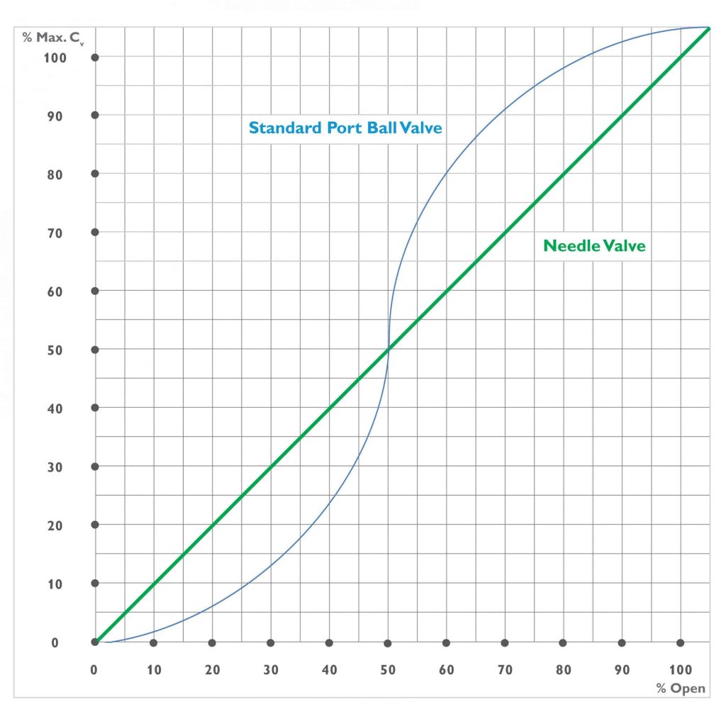
The graph below compares schematic flow curves. The red line depicts a Standard Port Ball Valve, and the blue line shows a Needle Valve. As seen in the lower left-hand corner of the graph, the Standard Port Ball Valve has a “Flow Jump” in its opening/closing phase. At about 5% of the opening, it has already reached 20% of its max flow. With a further 5%, it already reaches 30% of the max flow.
In comparison, the Needle Valve needs an opening of 20% to reach 20% of the max flow. This configuration offers a much higher grade of control.

Operating behavior of needle valves and ball valves
There is a vast difference in the manual handling of needle valves and ball valves:
- The operator can move the tip of a needle valve by turning the handle several times. This action moves the valve from the closed to open position.
- The ball valve splits the full range on a quarter-turn of the handle. Anyone who has ever moved a ball valve under working pressure can attest that it is harder to control this movement. And even more, if you need to apply a breakaway torque after not having it turned for a while. The partial movement intended can result in a much larger move than desired.
This quick opening and closing of a ball valve could thus cause immediate rise or fall of pressure.
The operator controls both pressure lines, but they are independent of each other. Thus, it can shock on the side of the measurement device with full line pressure. If that happens, it can damage the expensive electronic equipment.
The AS-Schneider Group has been a supplier of both valve technologies for many years. Thus, to be on the safe side, we recommend the use of a needle valve for natural gas measurement.
Image Source: © peterschreiber.media (Adobe Stock & AS-Schneider)
