There is no reason to specify DIN 19213 instead of IEC 61518
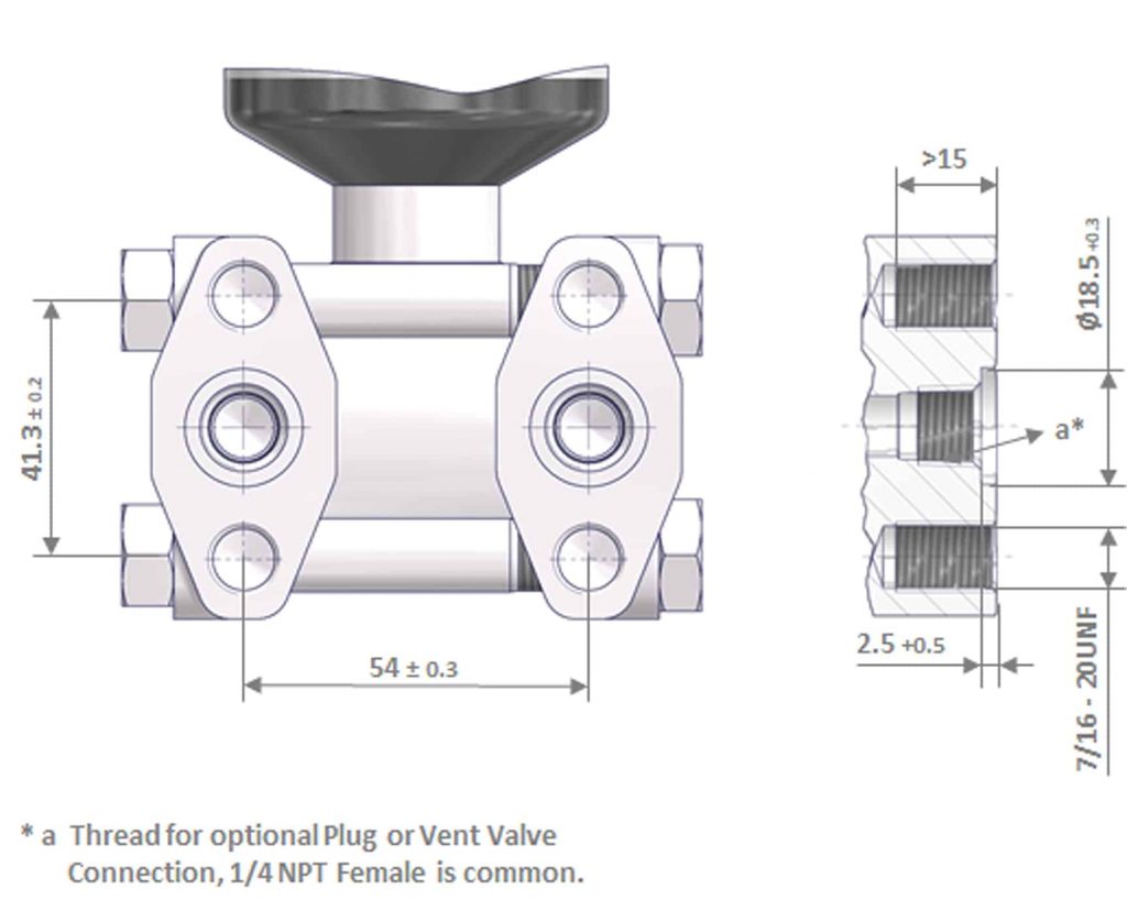
Transmitter interface
The transmitter interfaces of IEC 61518 and DIN 19213 are nearly identical. Only some minor tolerance modifications have been made. The most important change was concerning the thread size: 7/16-20 UNF instead of the metric sizes M10 and M12.
Note: As mentioned IEC 61518 has been issued in 2001, however metric threads are still available for ordering but there is no technical reason to use the metric threads.
Manifold interface
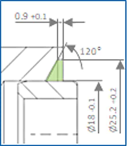
DIN 19213
Beveled groove with spigot
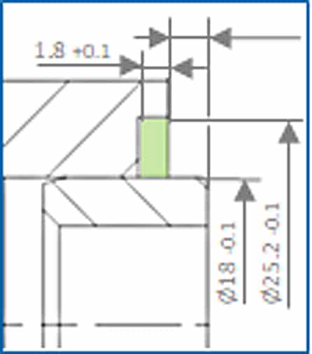
IEC 61518 Type A
Rectangular groove with spigot
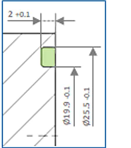
IEC 61518 Type B
Rectangular groove without spigot
Groove volume
DIN 19213
Max. 517 mm3
Min. 458 mm3
IEC 61518 Type A
Max. 469.5 mm3
Min. 429.9 mm3
IEC 61518 Type B
Max. 425.9 mm3
Min. 386.5 mm3
PTFE flat ring volume
DIN 19213
Max. 598.4 mm3
(Revision 1980)
Min. 511.7 mm3
(Revision 1980)
Max. 557.1 mm3
(Revision 1991)
Min. 519.4 mm3
(Revision 1991)
IEC 61518 Type A
Max. 577.7 mm3
Min. 539.4 mm3
IEC 61518 Type B
Max. 539.1 mm3
Min. 500.6 mm3
Ratio PTFE flat ring volume – Groove volume (worst case scenario)
| STANDARD |
MIN. RING VOLUME – MAX. GROOVE VOLUME |
MAX. RING VOLUME – MIN. GROOVE VOLUME |
|---|---|---|
| DIN 19213 (Revision 1980) | 99.0 % | 130.6 % |
| DIN 19213 (Revision 1991) | 100.5 % | 121.6 % |
| IEC 61518 Type A | 114.9 % | 134.4 % |
| IEC 61518 Type B | 117.6 % | 139.5 % |
What does this mean? Concerning the above mentioned worst case scenario the DIN 19213 flange connection will most probably start leaking in a short period of time – depending on pressure, temperature and fluid conditions. There is not enough seal ring material available to keep a leak-free flange connection.
All IEC 61518 flange connection options with either PTFE or Graphite flat ring or elastomeric O-Rings are designed and tested for the pressure – temperature rating mentioned in IEC 61518. So this is the standard which should be used only.
(Image source: © Andrey Popov/Fotolia & AS-Schneider)